Namaskar Dosto,
In previous artical i discussed about The internetworking problem.For networking we also need IP addresses inspite of networking technology.What is IP address? This is the main concern of this artical.I will discuss something about IP address.
IP addresses:- For any host, computer on a TCP/IP network, a unique id (32 bits in IPv4) written as a collection of 4 decimal numbers (dotted quad) between 0 to 255.
Ex. IP address: 132.64.48.56. Every device must have a unique IP address. All devices pertaining to a common network must reflect a common network portion of address that must be registered with the Internet community provided by some Internet Service Provider (ISP)
IP address class:
Class A: 0 + 7 network ID bits + 24 host ID bits
Class B: 10 + 14 network ID bits + 16 host ID bits
Class C: 110 + 21 network ID bits + 8 host ID bits
Class D: 1110 + 28 multicast address bits
Address formats:
network. local.local.local (for class A IDs)
network.network.network.local (for class C IDs)
IP address of a device MAC address (physical ID)
MAC address is a permanently stamped address. IP address is stored in a configuration file in the local disk.
Subnets:
A single network may be split into a multiple networks for internal use but appear as a single network to outsider. This is the concept of subnets.
Subnet mask:- An address such that when added to network address (in bitwise-and) splits the address into network + subnet + host address.
e.g. IP address: 12.11.10.9 subnet mask 255.254.0.0
Since the leading bit begins with 0, it’s a Class A network with address 12.0.0.0
00001100 00001011 00001010 00001001 IP
+ 11111111 11111110 00000000 00000000 Subnet
___________________________________________
00001100 00001010 | 00000000 00000000
Network is extended by 7 more bits. Therefore, this is subnet 10.
The remaining host part is 0.1.10.9 is the host address.
IP and subnet masks are often presented together in this format. e.g. Network address = 154.4.32.0 , subnet mask = 255.255.224.0. In this case, the network address can be written as 154.4.32.0/19
indicating subnet has 19 bits for the network portion of address, and has remaining 13 bits for host part.
Therefore, total number of subnets = -2 = 6
Total numbe of hosts per subnet =
Classless Interdomain Routing (CIDR)
Classfull addresses waste a lot of addresses. Ideally, we could bunch similar network addresses together and reduce ARP table considerably. For a good example, see Tanenbaum
Some distinct networks:
a. 127.0.0.0 is used for loop-back address (typically in the form of 127.0.0.1)
b. When host address is either all 0s (4.2BSD) or all 1s (Unix OS standard), it’s considered a broadcast message.
c. For mobile objects, two addresses: Home address (permanent), and a care-of address. Used only for forwarding IP datagrams and admin functions. Higher layers never use them.
d. Care-of addresses two types: Foreign agent address, and Co-located care of address where mails are sent directly to the device on a foreign net.
TCP/IP includes a protocol suit ARP (Address Resolution Protocol) to map IP addresses to physical addresses by network administrators. The constructed table is called ARP cache.
RARP = Reverse Address resolution Protocol permits the inverse mapping from MAC to corresponding IP address. Hosts such as diskless workstations only knows their MAC addresses when booted but not their IP addresses. This must be obtained from an RARP server source. (RFC 903 for details).
Ok friends......i hope u get this artical.leave your comments.I need your support to share something useful.
Thanks for visiting.................

The Internetworking Problem.....
Hello friends,
In this artical i will discuss internetworking problem.As we all know internet become a main part of everyone's life.Without it we suffer much in today.As a mca student it become my soul.What problem face by us during networking.I am here to discuss that major problem.
Problem:- How to interconnect different networks together?
Look into IP, TCP, end-to-end issues.
The Internetworking Problem. Many different networks.
Link heterogeneity issue. Single-link LANs do not scale well over hundreds of miles distances. LAN switching for unknown destination implies broadcasting, a poor scheme in large nets.
Link technology: LANs, point-to-point, Packet radio, wireless, satellites. An extremely heterogeneous community.
Challenge: Design a scalable network infrastructure that connects different types of smaller networks enabling packet flows between hosts across different nets.
Issues to reckon:
■ Addressing: Each net may have its own addressing approach. Ethernet uses 6-byte ID, Telephone uses 10-digit numbers.
Gateways:
Primarily a protocol converter. It interfaces distinct networks with different characteristics.
Two types: Translation GW, and Unified Network Layer.
Translation-based Gateways: translates packet headers and protocol from one network to another seamlessly.
Problems:
a. Feature deficiency: Not all features are “preserved” as one moves from one net to another. Not all features are supported by the translation.
b. Poor scalability: Translation = where is the number of networks connected. Untenable at large networks
Internet Design principles:
Identify key parameters (a small number) which must be preserved through translation. All hosts and networks must implement them. Check the seminal paper: “End-to-end arguments” http://www.reed.com/Papers/EndtoEnd.html
Universality principles:
U1. IP-over-everything. A standard network protocol IP would be used as Internet Protocol. Must have a standard well-defined addressing convention. Then scaling is not an issue.
U2. Best-effort service model. All packets are treated alike, if any gets lost address this at the end, not inside the network to recover it. (Increases scalbility and throughput)
U3. End-to-end arguments. Keeps the interior of the network as simple as possible. Move all controls for reliability, congestion control etc. at the end-hosts. TCP functionality removed from Gateways.
Robustness principle:
R1. Soft-state inside the network. Refresh soft-states such as Router tables as often as possible. Thus, even if it gets lost once in a while, it’s no big deal.
R2. Fate sharing. Even if a GW crashes, the end-to-end communication must continue. The GW state is a soft-state, and it shouldn’t share its fate with end-hosts.
R3. Conservative-transmission/Liberal reception. Be conservative in what you send, be liberal in what you receive. What does a TCP sender do when it sees an ACK for a message it didn’t expect?
Weaknesses:-
Internet architecture has its own weaknesses.
■ Architecture relies heavily on the trustworthiness of end-systems. How does one build a trusted networks when hosts (or a subset of them) couldn’t be trusted?
■ Greedy sources aren’t handled well. TCP does a good job in sharing its bandwidth, but more and more traffic isn’t TCP
■ Security issues have been neglected
■ Administration and management tools are not all that matured
■ Incremental deployment. Not a fundamental problem, but ought to be recognized by every protocol designer.
■ Bandwidth and Latency: Link bandwidth would vary from net to net from bits/sec to Gb/sec. Latencies can be from μs to several secs.
■ Packet size: In general varies between networks
■ Loss rates & QoS: All networks vary considerably in these. These depend on traffic volume, congestion, service demands, …
■ Packet routing: Routing of packets may be handled differently by different nets.
The original TCP/IP (Cerf & Kahn).
■ Key idea. Gateways. Reject translation in favor of gateways.
■ IP over everything.
■ Standard packet header format
■ Gateways perform fragmentation, reassembly at end-hosts
■ TCP: Process-level communication via TCP, a reliable, in-order, byte-stream protocol. Original TCP did reassembly; now it’s done at the receiver. TCP and IP were tightly interwined originally, now they are separate.
■ How to launch/sustain/deliver multiple TCP between two processes? Original design didn’t consider this.
1. Use same IP packet for multiple TCP segments?
2. Use different IP packets for different segments?
■ 2 is simpler than 1. It’s easier to demux and out-of-order packets are difficult to handle in 1. Demux key is the port number of the receiving process.
■ Sliding window, cumulative ACK-based ARQ protocol.
■ Window-based flow control
■ Heavily dependent on connection setup and release scheme.
■Way off the mark on accounting issues
■One line summary
Sniffer.............


Good morning friends,
The main scope of this artical is to detect the lost mobiles. Each and every day thousands of mobiles get misplaced or lost, though effective way for the blocking of the lost mobile to prevent unauthorized person from making and receiving the calls has been done by the manufacturers of the mobile with the help of International Mobile Equipment Identifier (IMEI) has been done but however there has been no development or very little progress for the detection of the misplaced mobile phone.
For the detection of lost mobile SNIFFER plays a vital role .The sniffer device has to be designed precisely and size should be reduced for easy mobility for the purpose of detection .The device can be called as a mobile Base station that includes Sniffer Base station, Unidirectional antenna , Tracking software. The sniffer is a small base station that includes transceiver section.It should operate at a frequency which is much different from the frequency of the current cell in which the operation of detection is being carried out. The directional antenna is an important device that is to be designed and used as it plays a major role.
There are certain boundary conditions that have to be qualified for the identification of lost mobile like the power of the mobile should be good enough, the mobile phone should not be in the shadow region but however this method using modern technologies and devices.
Our paper seems to be a bit costlier for initial setup but the cost is gradually reduced when effectively and efficiently utilized for the purpose of detection.
Introduction
One of the most interesting things about cell phone is that it is really a radio an extremely sophisticated radio, which uses some band of frequency that has the basic working similar to the ordinary cordless phone. The mobile cellular communication has been appreciated since its birth in the early 70’s and the advancement in the field of VLSI has helped in designing less power, smaller size but efficient transceiver for the purpose of communication.
But however the technology has not yet answered the loss or misplacement of the lost mobile phone which is significantly increasing. In this paper we discuss the problem and the probable solution that could be done. The IMEI number is a unique number that is embedded in the mobile phone the main purpose of which is the blocking of calls that is made by unauthorized person once the mobile is reported as stolen but here we use it effectively for the purpose of detection.
2. ABOUT IMEI :
The GSM MoU’s IMEI (International Mobile Equipment Identity) numbering system is a 15 digit unique code that is used to identify the GSM/DCS/PCS phone. When a phone is switched on, this unique IMEI number is transmitted and checked against a data base of black listed or grey listed phones in the network’s EIR (Equipment ID Register). This EIR determines whether the phone can log on to the network to make and receive calls. To know the IMEI number the *#06# has to be pressed, the number will be displayed in the LCD screen; it is unique to a mobile phone. If the EIR and IMEI number match, the networks can do a number of things.
For example grey list or blacklist a phone:
1. Grey listing will allow the phone to be used, but it can be tracked to see who has it (via the SIM information).
2. Black listing the phone from being used on any network where there is an EIR match.
3. DESIGNING FOR THE SNIFFER
As stated this proposal is about the detection of lost mobile phone and for this purpose we are designing a new device called the Sniffer. The sniffer device has to be designed precisely and size should be reduced for easy mobility for the purpose of detection.
The device can be called as a mobile base station that includes the following important components:
1. Sniffer base station
2 .Unidirectional antenna
3 .Tracking software
3.1 SNIFFER BASE STATION:
The sniffer is a small base station, it includes transceiver section. It should operate at a frequency that is much different from the frequency of the current cell in which the operation of detection is being carried out.
Some of the main important things are the frequency that has to be generated by the transceiver section is around 900MHz range which is a VHF range and it is necessarily to design the oscillator circuit for that frequency range .Another important is the cooling that has to be provided to the circuit while designing the circuit that is to be operated at 900MHz range of frequency. Hence proper design of base station is an important thing in the design of the sniffer. Mobile phones as well as the base station has low power transmitter is also transmitting at low power. The transmitter of the sniffer has to be a low power transmitter. This helps in the process of reducing the interference of the device with the devices that are in the other cells.
3.2 DESIGN OF UNIDIRECTIONAL ANTENNA:
Though the transceiver in a sniffer plays an important role in the detection of the mobile phone but however it is the directional antenna that has a major role in the design of the transmitter. The directional antenna acts as the eyes for the sniffer for the purpose of the detecting the lost mobile phones. Hence the proper design of the directional antenna is required. Antenna is a device which works at specified frequencies range for transmitting or receiving the data signal. In general, antennas transmit power depending on lobe pattern which varies from one antenna to the other. The lobe pattern is a two dimensional diagrams that is used to show radiation pattern. Radiation pattern of directional antenna is shown in fig1.
In addition to this it is necessary that the transmitter should be a low power transmitter. The Gain and directivity are intimately related in antennas. The directivity of an antenna is a statement of how the RF energy is focused in one or two directions. Because the amount of RF energy remains the same, but is distributed over less area, the apparent signal strength is higher. This apparent increase in signal strength is the antenna gain. The gain is measured in decibels over either a dipole (dBd) or a theoretical construct called an Isotropic radiator (dBi). The isotropic radiator is a spherical signal source that radiates equally well in all directions. One way to view the omni directional pattern is that it is a slice taken horizontally through the three dimensional sphere.
The graphical representation of Radiation pattern of the unidirectional antenna is shown in figure. The spherical co-ordination system has three main components for the pattern representation and they are (R, θ , Ф ) .The shape of the radiation system is independent of R, as long R is chosen to be sufficiently large and much greater than the wavelength as the largest dimension of the antenna. The magnitude of the field strength in any direction varies inversely with R. A complete radiation pattern requires the three dimensional representation. The other factors that are to be taken into account during the development of the antenna for the sniffer should be the gain and the directivity .As these features have a greater effect while designing the antenna. The gain of the antenna is defined as the ability of the antenna to radiate the power in a particular direction. The power radiated per unit area in any direction is given by the pointing vector and is equivalent to
E2/η2 W/m2
Total of the power that is being radiated by the antenna is given as
W=∫ΦdΩ
The average power that gets radiated is given as
Φ(avg)=W/4π (watts per steradian)
The Directivity of the antenna is the direction in which there is maximum gain for the radiation that is being radiated, the gain of the antenna is given as a function of the angles. The directivity value is constant for a particular direction. In addition to the directivity and the gain of the antenna the other important thing that has to be taken into account is the power that is being radiated by the antenna. The total power is given as W and is the summation of the radiated power and the ohmic loss of the antenna. Here the Wl represents the ohmic losses of the antenna.
Wt=Wr+Wl
The power gain of the antenna is given as
gp=4πΦ/wt
The ratio of power to the directivity is referred as a measure of efficiency of the antenna
gp/gd=Wr/(Wr+Wl)
The power radiated by the antenna should be properly designed as this causes more penetration of the electromagnetic radiation and thus it might have some effect in the near by cells.
The effective area of the antenna is another important factor that is mainly required in the receiving antenna and it may be referred as the effective aperture or capture area and is related to the directive gain of the antenna through the relation
A=gdλ2/4
Since the sniffer device that is constructed is a device that has both the transmitting and the receiving antenna. Effective gain has to be taken into account and this shows the ability of the antenna to capture the signal that the lost mobile is transmitting.
3.3 SOFTWARE FOR THE TRACKING:
The software part plays a major role in the tracking of the lost mobile phone It is the base for the antenna to track the lost mobile the main feature of this software is that it helps in the process of creation of the data base and this is mainly done using a Random Access Memory. The mobile phone that is lost has certain IMEI number that is embedded in the chip. This RAM of the sniffer device stores the IMEI number of the lost mobile phone. Thus this acts as a data base or the directory of the lost mobile phone number/The software that is to be designed in such a way that the software has the input as the IMEI number of the lost mobile phone from the RAM and this ID done using the SQL query that fetches the IMEI number. After getting the input of the lost mobile phones IMEI number it checks the comport for getting the information whether it obtains any signaling information from the lost device that might respond to the signal sent by the sniffer
The programming is done with C or Java. However the C is most preferred as it is easily embedded with the chips. With VB the front end is designed. The oracle SQL is the back end as it helps in retrieving the input data from the RAM using the query. But however the sample program that we have designed does not use the oracle it takes the input directly from the keyboard and this is an example and a dummy program that has been created that helps in the understanding of how the device would work.
4. WORKING OF THE SNIFFER DEVICE
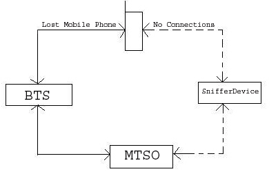
The sniffer is basically a transceiver that works in the frequency which is in the special unused range that is operated by the service provided or it can designed to operate at a frequency that is of much different frequency than the one that is being used by the nearby cells as there may be possibility of interference by the device with the devices in the nearby cells. The working for the device is as follows. The fig 2 &3 shows the working of the sniffer ; as given in the fig2 it gives the normal operation of the mobile with the base station and there is a BTS that acts as a middle man in the process of communication between the mobile and the MTSO which is popularly known as MSC or Mobile Switching Centre .There is always a two way communication between devices and before the establishment of the communication the authentication of the SIM card that has the IMSI or the International Mobile Subscriber Identifier .This IMSI number helps in the authorization of the user. The second authentication is the authentication of the handset, which is done in EIR or the Equipment Identifier Register. This register is located at the MSC and it contains the IMEI number of the lost handset and if the signal is obtained from the normal one then the two way communication is established.
The IMEI of the lost mobile phone number once has been reported to the service provider, who keeps in track of the record of lost mobile phones. The MTSO or the MSC which keeps in track of all the mobile phones with IMEI number and the IMSI number has the information of the lost mobile phones location which means the location of the cell where the lost device is because of the two way communication with the device the BTS of the lost device is known to MSC. From this information regarding the cell in which the device is located the sniffer device is introduced.Fig 3 . The connection of the sniffer device with the lost mobile phone.
Here the signal strength of the received signal is obtain antenna pattern is plotted once the signal of the mobile is obtained. The no. of antenna pattern for different position of same mobile phone is used to find the exact location. But however in this method the directional antenna used much be of a very small beam width this helps in more accurate process of detection. Fig4 the sniffer shown in fig tries to communicate with the lost mobile.
After getting connected with the mobile it creates a virtual cell pattern and thus helps in the detection of lost mobile phones.
5.CONCLUSION:
Since the boom of the mobile phone for the purpose of the communication there has been a large no. of complaints regarding the mobile phone that is being lost and there has been no effective method developed for detecting the lost device. The given paper dealt about the idea of development “Sniffer for the detection of lost Mobile phones” paves a way by means of which the lost mobile phones can be recovered. But the process of detection is yet to be developed through the software and demo has been developed and is with the authors. The demo has been written in VB that gives the over view of how the lost mobile is being detected and the software has been written in C. The SQL has to be used for the purpose of querying and the internal architecture is of lesser complexity compared to the base station as this mainly involves the control signal and there is no need for the voice process.
The design involved the following:
Design of the sniffer base station design of unidirectional l antenna, development of software for tracking. Though this method appears to be a little bit complex involving the design of the sniffer but however for large scale detection the overall effective cost of the design and the detection scales down.
There are certain boundary conditions or criteria that have to be qualified for the identification of the lost mobile like the power of the mobile should be good enough , the mobile phone should not be in the shadow region etc., but however this method can be improved by using modern technologies and devices.
APPENDIX
IMEI: International Mobile Equipment Identifier.
SNIFFER: The small transceiver used for detecting lost mobile phone.
IMSI: International Mobile Subscriber Identifier.
BTS: Base transceiver station.
MTSO: Mobile Telephone Switching Office.
MSC: Mobile Station Switching Controller.
Ok friends,its all about sniffer device which i want to discuss.I hope it was quite understandable.Please leave comments in favour if you like and you can give suggestion also if I did any mistake.............
I will post new artical soon.....keep on watching.........bye
Subscribe to:
Posts (Atom)